Difference between revisions of "Example Stereo Mesh"
From BoofCV
Jump to navigationJump to searchm |
m |
||
| Line 1: | Line 1: | ||
<center> | <center> | ||
<gallery heights=350 widths=350 perrow=4 > | <gallery heights=350 widths=350 perrow=4 > | ||
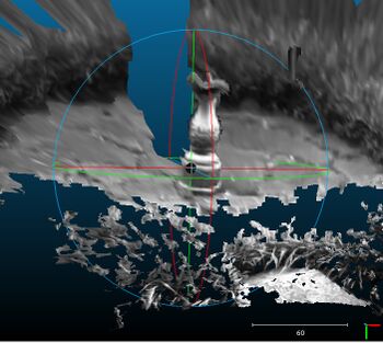
File:Example_disparity_mesh_cloudcompare.jpg| Mesh generated | File:Example_disparity_mesh_cloudcompare.jpg| Mesh viewed in Cloud Compare and generated from a stereo disparity image. | ||
</gallery> | </gallery> | ||
</center> | </center> | ||
Latest revision as of 18:49, 2 September 2022
Shows you how to convert a disparity image into a 3D mesh. Meshes are typically easier to view in 3rd party libraries.
Example Code:
Concepts:
- Stereo Disparity
- Filtering
Related Examples:
Example Code
/**
 * Example showing how you can convert a disparity image into a 3D mesh.
 *
 * @author Peter Abeles
 */
public class ExampleStereoMesh {
	static int disparityMin = 5;
	static int disparityRange = 60;

	public static void main( String[] args ) {
		String calibDir = UtilIO.pathExample("calibration/stereo/Bumblebee2_Chess/");
		String imageDir = UtilIO.pathExample("stereo/");

		StereoParameters param = CalibrationIO.load(new File(calibDir, "stereo.yaml"));

		// load and convert images into a BoofCV format
		BufferedImage origLeft = UtilImageIO.loadImage(imageDir, "sundial01_left.jpg");
		BufferedImage origRight = UtilImageIO.loadImage(imageDir, "sundial01_right.jpg");

		GrayU8 distLeft = ConvertBufferedImage.convertFrom(origLeft, (GrayU8)null);
		GrayU8 distRight = ConvertBufferedImage.convertFrom(origRight, (GrayU8)null);

		// rectify images
		GrayU8 rectLeft = distLeft.createSameShape();
		GrayU8 rectRight = distRight.createSameShape();

		// Using a previous example, rectify then compute the disparity image
		RectifyCalibrated rectifier = ExampleStereoDisparity.rectify(distLeft, distRight, param, rectLeft, rectRight);
		GrayF32 disparity = ExampleStereoDisparity.denseDisparitySubpixel(
				rectLeft, rectRight, 3, disparityMin, disparityRange);

		// Remove speckle and smooth the disparity image. Typically this results in a less chaotic 3D model
		var configSpeckle = new ConfigSpeckleFilter();
		configSpeckle.similarTol = 1.0f; // Two pixels are connected if their disparity is this similar
		configSpeckle.maximumArea.setFixed(200); // probably the most important parameter, speckle size
		DisparitySmoother<GrayU8, GrayF32> smoother =
				FactoryStereoDisparity.removeSpeckle(configSpeckle, GrayF32.class);

		smoother.process(rectLeft, disparity, disparityRange);

		// Put disparity parameters into a format that the meshing algorithm can understand
		var parameters = new DisparityParameters();
		parameters.disparityRange = disparityRange;
		parameters.disparityMin = disparityMin;
		PerspectiveOps.matrixToPinhole(rectifier.getCalibrationMatrix(), rectLeft.width, rectLeft.height, parameters.pinhole);
		parameters.baseline = param.getBaseline()/10;

		// Convert the disparity image into a polygon mesh
		var alg = new DepthImageToMeshGridSample();
		alg.samplePeriod.setFixed(2);
		alg.processDisparity(parameters, disparity, /* max disparity jump */ 2);
		VertexMesh mesh = alg.getMesh();

		// Specify the color of each vertex
		var colors = new DogArray_I32(mesh.vertexes.size());
		DogArray<Point2D_F64> pixels = alg.getVertexPixels();
		for (int i = 0; i < pixels.size; i++) {
			Point2D_F64 p = pixels.get(i);
			int v = rectLeft.get((int)p.x, (int)p.y);
			colors.add(v << 16 | v << 8 | v);
		}

		// Save results. Display using a 3rd party application
		try (OutputStream out = new FileOutputStream("mesh.ply")) {
			PointCloudIO.save3D(PointCloudIO.Format.PLY, mesh, colors, out);
		} catch (IOException e) {
			throw new RuntimeException(e);
		}
	}
}
